Flat rooflight falls, drainage and ponding
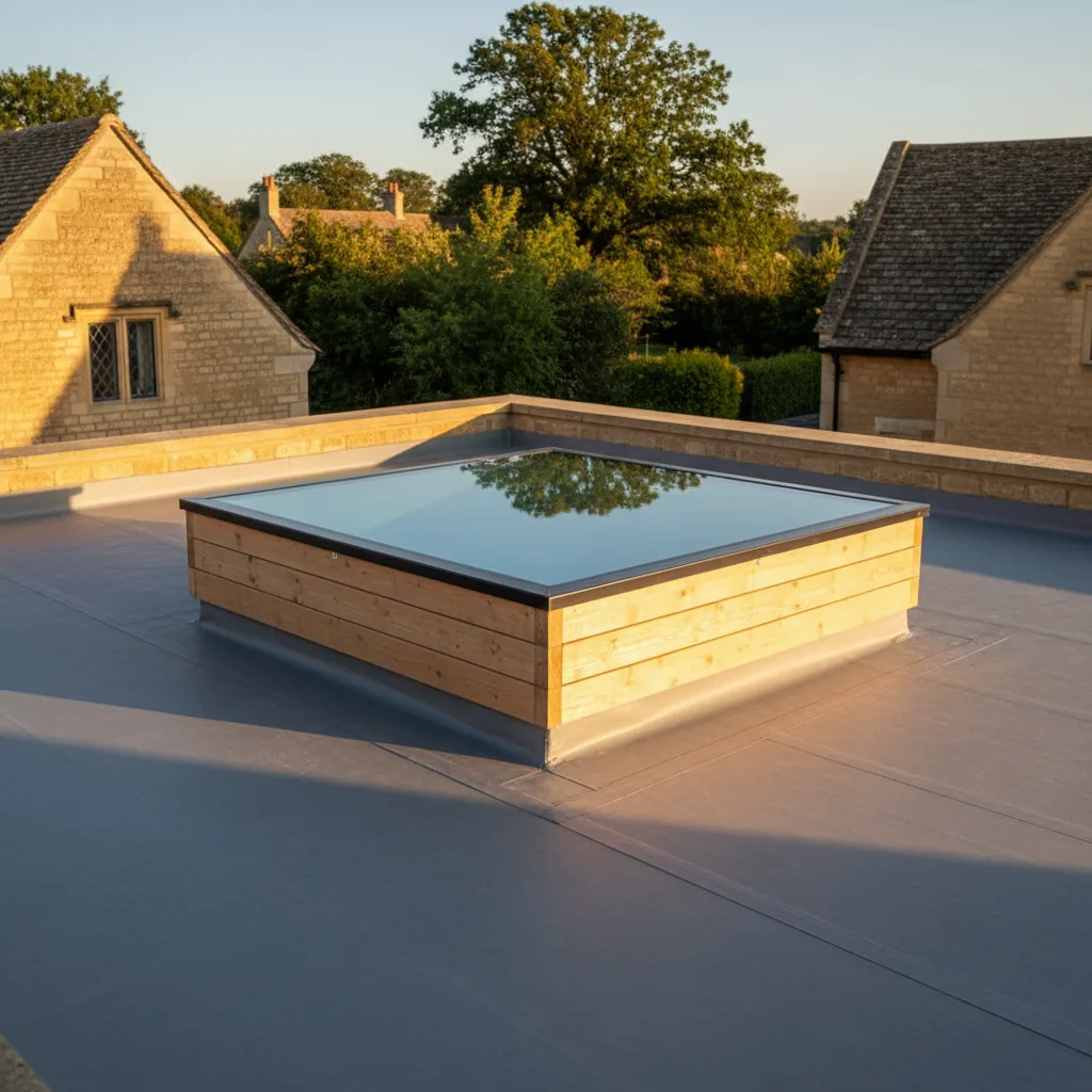
A flat roof with a rooflight in it has to move rainwater around a solid obstruction that was not there when the roof was designed. That is the whole of the problem. A kerb 900mm by 1800mm sitting in the middle of a 20 square metre roof blocks roughly a tenth of the surface, splits the flow into two streams, and creates a length of upslope timber that every drop arriving from above has to travel past. Get the falls and the outlet arrangement right and the water is gone within minutes of the rain stopping. Get them wrong and there is a shallow pond sitting against the kerb from November to March. The general sequence of a flat roof installation is set out on the flat roof rooflight installation page. This one is about water: how much of it arrives, where it is meant to go, and what happens at the one point on the roof where it cannot travel in a straight line.
What a fall has to achieve once a kerb is standing in it
On an open flat roof, a single plane falling one way to a gutter or an outlet is enough. Every square metre drains across every square metre downslope of it, and the water leaves.
Put a kerb in and that stops being true. The kerb is watertight by design, so nothing crosses it. Water arriving from the upslope half of the roof has to be steered around both sides, and the two streams have to rejoin below without either of them slowing to a stop. The fall now has to work in more than one direction at once, which is a design decision rather than something that happens by itself.
The practical consequence is that the falls on a roof with a rooflight in it are worked out before the insulation is ordered, not adjusted afterwards with an extra layer of chippings.
Rainfall over Gloucestershire, and the litres a small roof actually moves
Design figures for domestic flat roofs in this part of the country usually sit around 75mm of rain an hour for a short, intense burst. That works out at roughly 0.021 litres per second for every square metre of roof.
A modest rear extension of 24 square metres is therefore shifting about half a litre a second in heavy summer rain. That sounds trivial until you picture it arriving over a two metre width and having to squeeze through a 300mm channel between a kerb and a parapet, at a gradient of one in eighty, through a strainer that has leaves in it.
Volume is rarely the difficulty on a domestic roof. Route is.
- Sealed unit, seated on the frame and never on the covering.
- Insulated kerb, 150mm from the finished surface to its top edge.
- Covering dressed up the kerb face and closed under the frame.
- Deck and roof structure. The kerb is fixed to this, not to the deck alone.
Catchment, and how one kerb turns a roof into three
The first thing worth drawing is the catchment: the area of roof whose water passes any given point.
A rooflight kerb divides that catchment. Everything upslope of the kerb becomes a defined area whose entire output must pass down one side or the other. Everything alongside becomes two narrow strips carrying more water per metre of width than any other part of the roof. Everything downslope receives what the strips deliver plus its own.
The strips are where roofs fail. They are narrow, they carry a disproportionate share of the flow, and they are also the places where debris collects because the kerb interrupts the wind that would otherwise sweep the surface clean.
The upslope face of the kerb, and the water that arrives at it head-on
Water travelling down the main fall meets the upslope face of the kerb square on. It has momentum, it has volume, and it now has to turn ninety degrees.
Where the top of the kerb is level and the roof is falling, that face is also the lowest point of a small triangular hollow. Water stands there. The covering at the base of the upstand is submerged for long stretches of the winter, and the laps in that exact area are the ones asked to hold back a standing head rather than shed a passing flow.
The answer is a diverter: a wedge of tapered insulation, or a firring arrangement, set behind the kerb to a steeper fall than the main roof, splitting the arriving water and pushing it out to both sides before it reaches the timber. It is a small piece of work, it costs almost nothing while the roof is open, and it is the single detail that most often distinguishes a dry kerb from a wet one after five winters.
Cutting tapered insulation on the diagonal, and the schemes that get drawn
Tapered insulation is supplied as a designed scheme, cut to a drawing, with each board numbered and laid in a set order. Around a rooflight the scheme stops being a set of parallel wedges and becomes a pattern of diagonals.
A typical arrangement puts a hip line running back at forty five degrees from each upslope corner of the kerb, so the arriving water is divided and thrown outward. Two valley lines then run down each side of the kerb, gathering the diverted flow and taking it on to the outlet. Below the kerb, the planes rejoin.
Schemes are usually cut to a nominal one in sixty so that the finished, built fall still clears one in eighty after deck tolerance, board thickness variation and the compression that happens under a walked-on surface. Designing to the minimum leaves nothing in hand.
Cross falls, valleys and the line where two planes meet
Every valley on a flat roof is a line where two planes intersect, and the fall along that line is always shallower than the fall of either plane.
Two surfaces each falling at one in forty, meeting at forty five degrees, give a valley falling at roughly one in fifty six. Meet them at a shallower angle and the valley gets flatter again. This is the arithmetic that catches people out: a roof can be built entirely at a compliant gradient and still contain a line that drains at half the rate anybody intended.
Where a valley runs alongside a rooflight kerb for two or three metres, that line wants checking on the drawing before the boards are cut.
Outlet sizing, and what a spigot of a given diameter carries
An outlet on a flat roof works at a very shallow head of water, which is the opposite of the condition a drainpipe is usually sized for. Capacity is governed by the depth of water sitting over the grating, and on a roof that depth is deliberately small.
| Outlet | Typical flow at shallow head | Roof area served at 75mm/hr | Where it suits |
|---|---|---|---|
| 50mm spigot | Around 1 litre/sec | Up to roughly 45 sq m | Small canopy or porch roof |
| 63mm spigot | Around 1.5 litres/sec | Up to roughly 70 sq m | Single rear extension, one outlet |
| 75mm spigot | Around 2.5 litres/sec | Up to roughly 115 sq m | Larger flat roof or a shared parapet gutter |
| 110mm spigot | Around 5 litres/sec | Up to roughly 230 sq m | Wide roof, or a single outlet by necessity |
Figures are indicative and depend on the outlet pattern, the strainer and the pipe below. What the table shows is that a domestic roof is almost never short of outlet capacity in the raw. It is short of an outlet in the right place.
Where the outlet sits in relation to the kerb
An outlet set too close to a rooflight kerb is awkward for two reasons. The covering has to turn a corner at the kerb and dress into a sump within a short distance, and there is rarely enough room to form both details properly. Two demanding details crowded into the same 200mm of covering is how water finds its way in.
As a working rule, keep at least 300mm of clear flat covering between the base of the angle fillet at the kerb and the edge of the outlet flange, and more where the outlet is a lead or GRP sump rather than a proprietary spigot. Where the roof simply is not big enough, the outlet moves rather than the rooflight.
The other consideration is the pipe below. An outlet in the middle of a room is a pipe through a ceiling, and on a small extension that usually decides the position long before drainage does.
Ponding, defined properly, and the forty eight hour test
Ponding is not simply wet roof. The recognised definition is water still standing more than forty eight hours after rain has stopped, under normal drying conditions.
Some residual water on a flat roof after a downpour is expected and harmless. A film that has gone by the following afternoon is a roof working correctly. A pool 15mm deep against a kerb that is still there on Wednesday after Sunday’s rain is a defect, and it will not improve on its own because standing water attracts silt, silt holds water, and the hollow deepens.
Deflection, and the pond that appears after the roof was signed off
A timber flat roof deflects under load. Joists are commonly sized to a deflection limit of around one three-hundredth to one two-hundred-and-fiftieth of the span, which on a 3.6 metre span allows something between 12 and 14mm of sag at mid span.
Add a rooflight and the loading changes. A 1200 by 1800 glass unit with a triple laminated build-up can weigh 150kg or more, and it is carried on trimmers that are themselves carried by two joists. Those two joists now deflect further than their neighbours. The roof surface dips locally, and it dips exactly where the water was supposed to be flowing past.
This is why the trimming around a heavy unit is sized as a structural exercise rather than by eye, and why a roof that drained perfectly before a unit went in can pond afterwards.
What standing water does to each covering, and to the timber below
Coverings tolerate water differently, and none of them like it indefinitely.
- Reinforced bitumen membrane: the mineral surfacing softens and washes off, the exposed bitumen weathers faster, and laps that were tested against running water are asked to hold a head.
- Single-ply: generally the most tolerant, though standing water shows up any weld that was rushed, and prolonged immersion at a kerb corner is where a fault emerges first.
- GRP: laid as one continuous piece, so it copes well, but a pond sitting over a fibre-rich area can cause the resin to blister over time.
- Lead: standing water and lead is a poor combination, producing white carbonate deposits and, in bad cases, underside corrosion where condensate cannot escape.
Below the covering, a kerb that spends four months a year with its base in water carries damp into the timber at exactly the point where the fixings and the vapour seal are.
Debris, moss and the outlet that silts up over three winters
Drainage is designed for a clear roof and used on a dirty one. Under a mature lime or sycamore, common enough on Gloucester’s Victorian streets and through Cheltenham, a strainer can be more than half blocked by the end of November.
A rooflight makes this worse in a specific way. The kerb shelters a strip of roof from wind, so leaves that would blow clear settle in the lee of it and stay. Moss follows on a north-facing side. Over three or four winters that strip builds a mat that holds water even where the fall is correct.
Two clear inspections a year, one in late autumn and one in spring, is the realistic maintenance a flat roof with a rooflight in it needs.
Overflows, and the outlet that only earns its keep once
Where a flat roof is enclosed by parapets on more than one side, and Cheltenham’s Regency terraces are full of these, a blocked outlet has nowhere to spill. Water rises against the kerb instead.
An overflow set through the parapet at a level above the design water line and below the top of the rooflight upstand gives the roof somewhere to go. It also gives an unmistakable visual warning, because water pouring out of a hole in a parapet wall gets noticed in a way that a slowly rising pond does not. On a roof carrying a rooflight, the overflow level is set with reference to the upstand height rather than the parapet coping.
Measuring the falls on a roof that already exists
Before a rooflight is designed into an existing flat roof, the falls have to be measured rather than assumed. Old roofs fall in directions their builders never intended.
A rotating laser and a staff will give levels across the whole surface in twenty minutes, and the pattern usually tells its own story: an original fall towards the rear, a later extension that fell the other way, and a dished area in the middle where a joist has taken a permanent set. Once the levels are on paper, the rooflight position can be chosen to sit on the high side rather than the low one, which is often the cheapest drainage improvement available.
Where the roof is genuinely level, or falls the wrong way, the fall gets rebuilt as part of the job rather than worked around.
Gloucestershire roofs, and where the water problems are local
Victorian rear additions through Gloucester, Tredworth and Barton fall towards a shared valley or a hopper on a party boundary, often with an original fall of little more than one in a hundred. Fitting a rooflight into one of these usually means re-forming the fall across the whole roof rather than a strip of it.
Cheltenham lead flats behind parapets drain to a single outlet, sometimes one shared with the house next door, and there is frequently no overflow at all. That combination decides a great deal about where a kerb can sit.
In the Severn Vale, the flood history makes homeowners understandably wary of anything involving standing water, and it is a reasonable instinct: the ground water table is high, drying conditions in winter are poor, and a pond that would clear in a week on the wolds sits for a fortnight in Tewkesbury.
Forest of Dean roofs around Coleford and Cinderford get more rain and more leaf fall, and roofs on the exposed wolds hold snow longer, which is a related but distinct problem covered on the snow and standing water page.
What the survey records before a unit is ordered
Drainage is settled at survey stage because almost none of it can be adjusted once the covering is back on.
- Levels across the existing deck, taken with an instrument rather than a spirit level.
- The position, size and condition of every outlet, and whether an overflow exists.
- Joist direction, span and depth, and the deflection the finished unit will add.
- The catchment each outlet serves once the kerb is in place.
- Evidence of previous ponding: silt lines, moss growth, staining on the covering.
- Whether the tapered scheme needs redesigning around the new opening.
Those measurements produce a drawing that shows the falls, the hips and valleys around the kerb, and where the water leaves. It goes to the client with the fixed price, and it is what the roof is then built to.
Next on this subject.
- Guide Upstands, kerbs and warm roof build-ups On a warm roof the kerb is not a small timber trim around a hole. It is a box roughly…
- Guide Walk-on rooflights and where they make sense A walk-on rooflight makes sense in one situation: where the surface above a room has to be usable, and the…
- Guide Single-ply, felt and GRP roofs around a rooflight Four waterproofing systems account for nearly every flat roof in Gloucestershire: single-ply membrane, reinforced bitumen membrane, glass reinforced polyester, and…
- Guide Flat rooflights on a cold roof build-up A rooflight can go into a cold roof, and thousands have. It is simply the harder of the two build-ups…
- Guide How many rooflights a flat roof extension needs For a flat roof extension used as a kitchen or a living space, a reasonable working figure is glazed rooflight…
- Guide Flat rooflight standard sizes and made to measure Flat rooflights come two ways. A stock size is a unit a manufacturer builds repeatedly to a published dimension, glazed…